
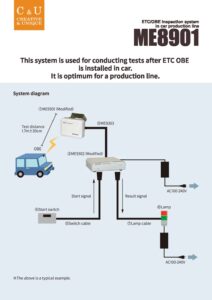
ETC/OBE Inspection System In Car Production Line ME8901
This system is used for conducting tests after ETC OBE is installed in car. It is optimum for a production line.
This system is used for conducting tests after ETC OBE is installed in car.
It is optimum for a production line.
- 1. System diagram
- 2. Specifications
- 2.1. 1.System configuration
- 2.2. 2.DSRC antenna (modified ME9301)
- 2.3. 3.Interface BOX (modified ME9302)
- 2.4. 4.Dedicated I/F cable ME9303
- 3. Operation
- 3.1. 1.Test operation
- 3.2. 2.Lamp result
- 3.3. 3.Modified ME9302 LED
- 4. Test contents
- 4.1. 1.Outline
- 4.2. 2.Flow
- 5. Library
- 5.1. Products Catalog
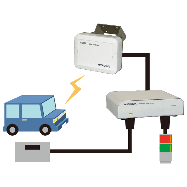
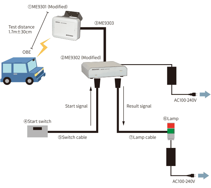
System diagram
Specifications
1.System configuration
The system consists of the following segments. Refer to “System diagram”
- DSRC antenna:ME9301 (Modified)
- Interface BOX:ME9302 (Modified)
- Dedicated IF cable:ME9303
- Start switch
- Switch cable(For connecting to the DI connector of modified ME9302)
- Lamp
- Lamp cable (For connecting to the DO connector of modified ME9302)
2.DSRC antenna (modified ME9301)
Performs a test by wirelessly communicating with ETC/OBE.
| Wireless section | Transmission frequency | 5.795GHz(CH1), 5.805GHz(CH2) |
|---|---|---|
| Transmission power | 0.6mW -50%/+20% | |
| Modulation method | ASK modulation | |
| Communication standard | ARIB STD-T75 compliant | |
| Power supply | Input voltage | approx. 6.6VDC |
| Power consumption | approx. 1.5W | |
| Interface | RS-422A compliant to connect with modified ME9302 | |
| Other | Operating temperature | -20 to 50℃ |
| Dimensions | 175Wx45Dx130H(mm)(excluding mounting bracket) | |
| Weight | approx. 1kg (including mounting bracket) | |
| Water proof | IP67 equivalent, suitable for outdoor installation | |
3.Interface BOX (modified ME9302)
Register and control a dedicated scenario in modified ME9302.
| Interface | RS-422A compliant to connect with modified ME9301 | |
|---|---|---|
| Power supply | Input voltage | approx. 9VDC (Using dedicated AC adaptor MA400. Input voltage from 100 to 240VAC.) |
| Power consumption | approx. 3.5W (including power consumption of modified ME9301) | |
| Operating LED |
| |
| DI (digital input) | Number of inputs | 1 |
| Input form | Photo coupler | |
| On-state voltage | +9V (Supplied inside modified ME9302) | |
| Input current at on-state | approx. 4mA | |
| DO (digital output) | Number of outputs | 2 |
| Output form | Photo MOS relay | |
| Maximum load voltage | 60V(AC,DC) | |
| Max. continuous load current | 210mA(150mA@50℃) | |
| On resistance | 2.3Ω(typ),4.0Ω(max) | |
| Off leakage current | 1μA(max) | |
| Operating time | 0.6ms typ., 2ms max @ only Photo MOS relay | |
| Recovery time | 0.06ms typ., 0.2ms max @ only Photo MOS relay | |
| Other | Operating temperature | 0 to 50℃ |
| Dimensions | 240(W)x60(H)x210(D)mm | |
| Weight | approx. 1.6kg | |
4.Dedicated I/F cable ME9303
| Length | 25m (Optional up to 100m max.) |
|---|
Operation
1.Test operation
Power is turned on by connecting each device and connecting the AC adapter of modified ME9302 to the power supply. After that, the scenario recorded internally is activated and the test can be started.
The test is started by pulling the start switch.
2.Lamp result
| Pass | Fail | |
|---|---|---|
| Green | Blinking for 5 seconds | Off |
| Red | Off | Blinking for 5 seconds |
3.Modified ME9302 LED
POWER LED
| State | Description |
|---|---|
| Solid | Power ON |
| Off | Power OFF |
OPERATING LED
| State | Description | Troubleshooting |
|---|---|---|
| Low speed (0.5Hz) blinking | Normal | - |
| Solid | Abnormal | Check that the ME9303 is securely connected to the modified ME9301 and ME9302, and then turn on the power again. |
| High Speed (2Hz) blinking | RSU carrier detection | Check if another DSRC tester (RSU) is running in the test area. |
Test contents
1.Outline
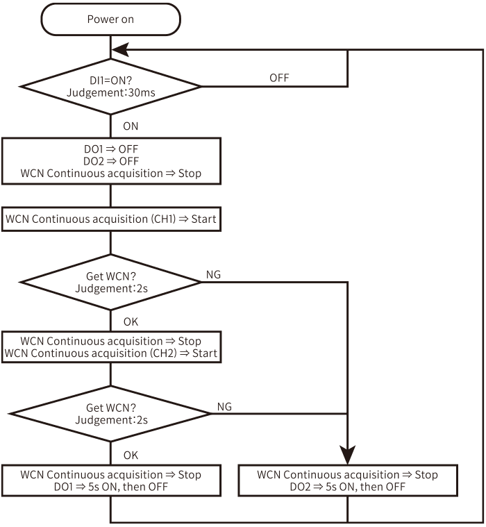
By input to DI1 from the start switch, CH1 (TX: 5.795GHz / RX: 5.835GHz) test start and then CH2 (TX: 5.805GHz / RX: 5.845GHz) test start continuously. The result is output to DO1 if it passes, and to DO2 if it fails.
If CH1 test fails, CH2 test will not start.
2.Flow
Library
Products Catalog


Please feel free to contact us.
If you want to verify 5G, customize a radio wave shield box, or need product repair, please do not hesitate to contact us about any small matter.