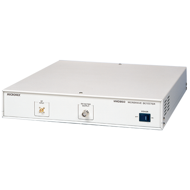
Microwave AM detector MMD850
-
- Detection of AM signal up to 2 to 8 GHz with a dynamic range of 30 dB.
- Evaluattion of W-CDMA, CDMA, GSM, PDC, PHS, wireless LAN, Bluetooth and wireless communication equipment including evaluation of ETC signals.
*This product is discontinued.
Features
- Faults of coaxial type AM detector
- Explanation of MMD850
Coaxial type AM detector has two disadvantages in the application indicated below :
Coaxial type AM detector in/out characteristics
The first is that the dynamic range is narrow. The curve is non-linear when the input is more than +5dBm or less than -10dBm as shown below. Therefore, the workable range is only +15dBm. It is provided, however, that when the peak level of input is less than +5dB, -6dBm for instance, the dynamic range is even narrower and drops to 4dB. Narrow dynamic range means that the waveform is collapsed.
Coaxial type AM detector equivalent circuit
The second is video output frequency band. The equivalent circuit of coaxial type AM detector (Rv = 1.5kohm, Co = 30pF) of a certain manufacturer is shown below. The case where observation is performed with this AM detector connected to an oscilloscope (RL = 1Mohm, CL2 = 25pF) using 1 meter coaxial cable (CL1 = 100pF) is taken into account.
Tr = 0.35 / fb = 2.2RvRL (Co + CL1 + CL2) / (Rv + RL)
Therefore, rising time Tr = 511 [ns] and frequency band fb = 685 [kHz]. It is learnt that the band is lower than what was imagined.
MMD850 block diagram
The block diagram of microwave AM detector MMD850 is shown below. When a microwave amplifier and linearizer are added to it, 30dB dynamic range is secured against signals of peak level more than -6dBm and up, and in addition, 10MHz bandwidth is secured without being affected by the load.
Against signals of peak level more than -6dBm, it is possible to observe signals without spoiling the dynamic range when fixed attenuator is located to the input. If three attenuators of 3dB, 6dB and 12dB are prepared, for example, it is possible to perform observation in at least 27dB dynamic range, against signals of peak level -6dBm to +15dBm. Furthermore, due to the fact that the output impedance of the linearizer is 50ohm, it is possible to perform observation without being affected by the load, when the output is terminated with 50ohm.
Input signals and detected output waveforms are indicated below. Example 1 is the case where continuous wave or FM wave of -6dBm is input. +1V DC voltage is produced as the detected output. Example 2 is the case where ASK signals of peak level -6dBm and bottom level -36dBm (modulation factor 94%) is input. A waveform of peak level +1V and bottom level +31.6mV is output.
Input signal and detected output waveform
Specification
Input characteristics | |
---|---|
Input frequency range | 2 to 8GHz *Available for 1 to 15GHz range as special order |
Optimum input level | -6dBm @ peak level |
Dynamic range | 30dB @ -6dBm input |
VSWR | less than 1.4 |
Input damage level | +13dBm |
Output characteristics | |
Output frequency range | DC to 10MHz @ -3dB |
Output voltage | +1.0V @ 50ohm load and -6dBm input |
Polarity | positive polarity |
output Impedance | 50Ω |
General | |
Power source | 90 to 132VAC, 50/60Hz (Option : 180 to 250VAC) |
Dimensions | 320(W) x 56(H) x 350(D)mm *excluding projections |
Standard accessories | Operation manual(1pc), Fuse(1pc), Power sourceCable(1pc) |
Option | |
180 to 250VAC Power source | |
Coaxial Cable MC201 | |
Coaxial Cable MC202 | |
Coaxial Cable MC203 | |
Fixed microwave attenuators (1 to 10, 12, 13, 15, 20dB) |
|
50Ω termination |
Library
*MICRONIX Corporation reserves the right to make changes in design, specification and other information without prior notice.