
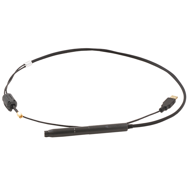
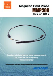
Magnetic Field Probe MMP500
Conducted disturbance noise measurement up to 9kHz low frequency.
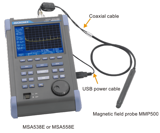
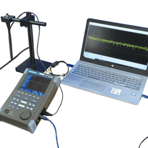
This conducted disturbance noise can be easily measured with MMP500 and signal analyzer MSA538E/MSA558E.
- 1. Product Description
- 2. Features
- 2.1. Optimum for measuring power electronics equipment.
- 2.2. Precompliance conducted disturbance noise measurement
- 2.3. Simple system
- 2.4. Compatible with various currents
- 2.5. Three detection modes
- 3. Measurement of conducted disturbance noise
- 3.1. 【Fig.1】Full measurement range 〔PosPK detection〕
- 3.2. 【Fig.2】962kHz noise 〔AV detection〕
- 3.3. 【Fig.3】70.7MHz noise 〔QP detection〕
- 3.4. Example of standard value
- 3.5. Rotation sensitivity
- 3.6. Distance sensitivity
- 4. Level calibration method
- 5. How to use signal analyzer
- 5.1. 1.Selection of measurement with MMP500
- 5.2. 2.If the limit line of the standard is close to the average noise level, set to a lower REF.
- 6. Option-Software
- 6.1. PC software MAS500
- 6.2. Logging software MAS510
- 6.3. PC software for EMI MAS530
- 7. How to use Magnetic Field Probe MMP500
- 8. Related products
- 9. Library
- 9.1. Products Catalog
Product Description
The LISN (Line Impedance Stabilization Network) is used for conducted disturbance noise test.
However, the magnetic field probe MMP500 was born based on the desire to perform this test more easily or to identify the noise source.
This conducted disturbance noise can be easily measured with MMP500 and signal analyzer MSA538E/MSA558E.
MMP500 was completed through joint development with the Tokyo Metropolitan Industrial Technology Research Institute.
Features
Optimum for measuring power electronics equipment.
Using this measurement system, it is possible to measure the conducted disturbance noise of the power supply line without electrical contact and without using LISN. In addition, the disturbance noise on PCB can be measured without contact. Optimum for measuring power electronics equipment used in such as automotive industry.
Precompliance conducted disturbance noise measurement
- If this system is used, the problem will be solved in the laboratory or outdoors.Save time and money.
- The signal analyzer MSA538E/558E can operate on battery (4 hours operating time ), so no AC power supply is required.
- The formal test may be performed once with the official test system (LISN) at the end.
Simple system
The conducted disturbance noise can be measured by a simple system with only the magnetic field probe MMP500 and signal analyzer.
Compatible with various currents
This probe can handle large current of DC and AC.
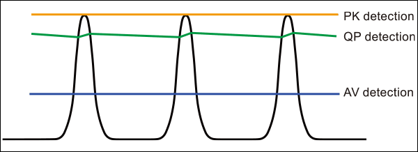
Three detection modes
This measurement system has three detection modes of PosPK (positive peak), QP (quasi-peak) and AV (average).
Measurement of conducted disturbance noise
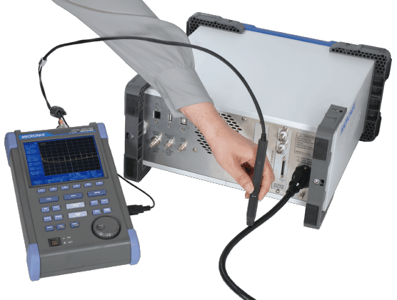
The following is an example of measuring conducted disturbance noise of a power supply line as a DUT (Device Under Test).
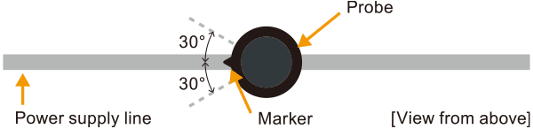
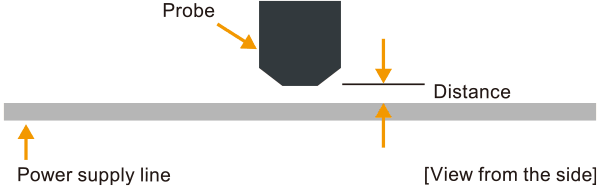
Measure placing the probe as perpendicular to the power supply line as possible, aligning the marker of the probe with the power supply line and making contact with the power supply line.
It affects the rotation sensitivity and distance sensitivity described on the following.
In this measurement example, the sheath’s thickness of the power supply line affects the distance sensitivity.
Assuming that the thickness of sheath is 0.5 mm, the disturbance noise is measured as 1.25dB lower because the distance sensitivity is 2.5dB/mm.
- REF:
Reference level. By lowering REF, the difference between the average noise level and the limit value can be increased. - RBW:
Resolution bandwidth. - VBW:
Video bandwidth. By using VBW, the average noise level is lowered, and the measurement dynamic range is expanded. - MaxHold:
Max Hold function. By using MaxHold, the noise that occurs intermittently can be captured.
【Fig.1】Full measurement range 〔PosPK detection〕
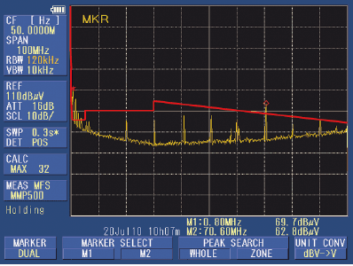
Grasp the noise generation situation in the full measurement range.
| Setting items | Setting value |
|---|---|
| REF | 110dBμV |
| RBW | 120kHz |
| VBW | 10kHz |
| MaxHold | 32 times |
【Fig.2】962kHz noise 〔AV detection〕
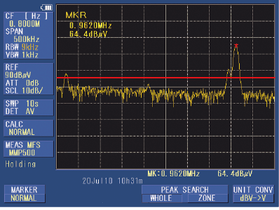
Measure the AV detection value of 962kHz noise that exceeds the limit line at PosPK.
| Setting items | Setting value |
|---|---|
| REF | 90dBμV |
| RBW | 9kHz |
| VBW | 1kHz |
| MaxHold | off |
【Fig.3】70.7MHz noise 〔QP detection〕
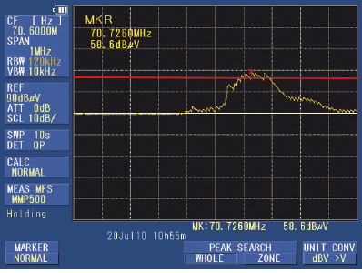
Measure the QP detection value of 70.7MHz noise that exceeds the limit line at PosPK.
| Setting items | Setting value |
|---|---|
| REF | 90dBμV |
| RBW | 120kHz |
| VBW | 10kHz |
| MaxHold | off |
Example of standard value
| Frequency | Limit value | RBW |
|---|---|---|
| 9 to 50kHz | 110dBμV | 300Hz(6dB) |
| 50 to 150kHz | 90 to 80 dBμV | |
| 150 to 500kHz | 66 to 56 dBμV | 9kHz(6dB) |
| 0.5 to 5MHz | 56 dBμV | |
| 5 to 30MHz | 60 dBμV | |
| 30 to 100MHz | 64 to 54 dBμV | 120kHz(6dB) |
Rotation sensitivity
The marker position of the probe shows 0°.
An error of approx. ± 1dB occurs in the range of 0 to ± 30°.
Distance sensitivity
As the probe moves away from the power supply line, the level of the disturbing noise decreases.
“approx. 2.5dB/mm@1 to 2mm, approx. 6.8dB@3mm and approx. 8.5dB@4mm”.
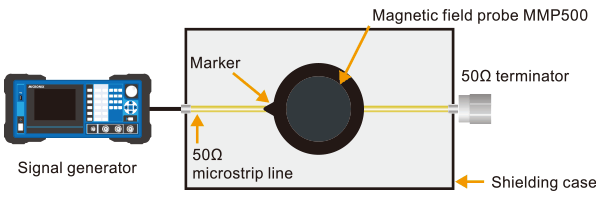
Level calibration method
The level is calibrated by the 50Ω microstrip line method.
The level is measured aligning the marker of magnetic field probe with the 50Ω microstrip line and contacting with it.
- Level calibration points: 10 points (linear interpolation is performed at frequencies other than the calibration points)
- Two kinds of calibration coefficients
- Typical calibration coefficient
Typical values of calibration coefficient are installed in the signal analyzer MSA538E/558E. Usually, the measurement can be done using this values (select “MMP500”). - Calibration coefficient attached to MMP500
Input the calibration coefficient attached to MMP500 from the PC using the command, and install it in “USER B” of MSA538E/558E. When using this, select “USER B”. More accurate measurements will be done.
The frequency characteristics of the MMP500 are calibrated in the signal analyzer MSA538E/558E, so that the correct measurement values can be observed on the screen.
*When using a spectrum analyzer other than MSA538E/558E, calibrate the measured level based on the attached calibration coefficient data.
How to use signal analyzer
1.Selection of measurement with MMP500
Select “Magnetic field measurement with MMP500” using MSA538E/558E function keys.
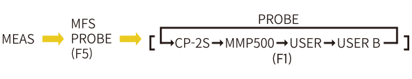
- MEAS:Measuring function
- MFS:Magnetic field strength measurement
- PROBE :Probe selection
- CP-2SA: 10MHz-3GHz magnetic field probe
- MMP500 :9kHz-100MHz magnetic field probe
- USER:Calibration coefficient of CP-2SA
- USER B:Calibration coefficient of MMP500
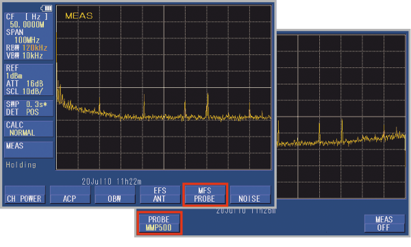
2.If the limit line of the standard is close to the average noise level, set to a lower REF.
| Frequency range | 9kHz to 100MHz (20kHz to 100MHz@MSA538E/558E) | |||||||||||||
|---|---|---|---|---|---|---|---|---|---|---|---|---|---|---|
| Maximum measurement level | 119dBμV | |||||||||||||
| Analysis and display equipment | MSA538E and MSA558E
Note RBW = 300Hz:3dB bandwidth |
|||||||||||||
| Level calibration method | 50Ω microstrip line method | |||||||||||||
| Rotation sensitivity | Deviation from 0° (marker position) approx. ±1.2dB@0 to ±30° |
|||||||||||||
| Distance sensitivity | Attenuation by distance from microstrip line (detector surface reference) approx. 2.5dB/mm@1 to 2mm, approx. 6.8dB@3mm, approx. 8.5dB@4mm |
|||||||||||||
| Operating temperature | 0 to 50°C (guaranteed at 23 ± 10°C) | |||||||||||||
| Operating humidity | less than 40°C/80%RH (guaranteed at less than 33°C/70%RH) | |||||||||||||
| Storage temperature | -20 to 50°C | |||||||||||||
| Dimensions | 14.5Φ×140mm (probe part) @excluding projections 10.5Φmm (detection portion) Total length:approx.1.2m | |||||||||||||
| Weight | approx. 70g (including cable) | |||||||||||||
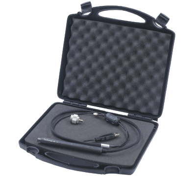
| Standard accessories | Storage case, Adapter MA306, Calibration coefficient data, Operating manual, Storage case |
|||||||||||||
| Options |
|
Option-Software
PC software MAS500
MAS500 is a software that controls the signal analyzer by the PC and displays the spectrum waveform on PC screen. MMP500 or USER B can be selected in M/F Probe of Measuring function , and the measurement results can be checked on the PC screen and saved.
Logging software MAS510
MAS510 is a logging software that collects the measurement data by uninhabited. It is optimum for watching an abnormal signal at night and recording the data by uninhabited for a long time.
PC software for EMI MAS530
MAS530 is a software used for conducted disturbance noise test. The frequency axis can also be displayed logarithmically. This is used in the “Conducted EMI test system MR2150” described in Related products.
How to use Magnetic Field Probe MMP500
Related products
Conducted EMI Test System MR2150
Pre-compliance test system for conducted EMI.
The development cost can be significantly reduced by debugging and evaluating EUT using this system before testing in the formal EMC site.
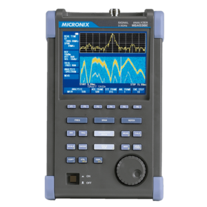
Handheld Signal Analyzer MSA538E
This is a model in which EMI measurement function is added to MSA538.
Measurement frequency : 20kHz to 3.3GHz
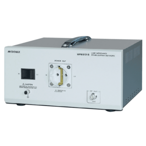
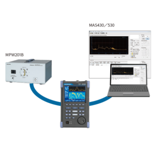
Line Impedance Stabilization Network(LISN) MPW201B
A test environment can be easily constructed in a limited space.
LISN is necessary to perform stably and reproducible disturbance noise measurement.
The impedance of the power source observed from EUT side is made constant by inserting LISN in the power supply line.
Power Line Noise Monitoring Equipment
Taking advantage of the characteristics of our magnetic field probes, which allow non-contact electrical measurement, the monitoring equipment combines a spectrum analyzer and logging software to monitor the noise of various secondary power supply lines.
Library
Products Catalog

Please feel free to contact us.
If you want to verify 5G, customize a radio wave shield box, or need product repair, please do not hesitate to contact us about any small matter.