The radio wave environment around the installation place must be measured before the wireless LAN is installed, and then the spot installed and the channel used are decided.
The setting of MSA338 is as follows when not specified especially.
- Center frequency[FREQ]:2.44GHz
- Frequency span[SPAN]:100MHz
- Resolution bandwidth[RBW]:1MHz
- Video bandwidth[VBW]:OFF
- Reference level[REFER]:-30dBm
- Sweep time[SWEEP]:0.1s
- Calculation[CALC]:MAX
However, the channel number 14 of the wireless LAN goes outside right of the screen if the center frequency is not changed to 2.45GHz, because the number of channels is assumed thirteen at the above setting. Moreover, it is necessary to increase or decrease the reference level by about 10dBm depending on the environment.
The electric field strength measurement can be done by pushing [MEAS] key and by selecting the electric field strength measurement mode by [F4] key, and then by selecting [M304] as an antenna by [F1] key. However, it is not necessary to use the electric field strength measurement mode if the unit of standard is dBm or W. It is better that the receiving power is measured in the channel power measurement mode because the antenna gain changes little at the span 100MHz.
The channel power measurement can be done by pushing [MEAS] key and by selecting the ch annel power measurement mode by [F1] key, and then by selecting BAND by [F1] key. Secon dly, the center (CNTR) and width (BAND) of the measured channel are set. The width, usu ally, is fixed to 20MHz. With the setting mentioned above , the receiving power of the sp ecified channel is displayed on the screen. However, if the channel power measurement mode is not turned off while measurin g, the measurement time becomes long.
Moreover, in the environment of the installation place where th e disturbance noise is inte rmittently generated, the measurement should be done for ten seconds or a few minutes by using the MAXHOLD function according to the state and the maximum value in this pe riod should be observed.
However, set the calculation node [CALC] to NORM when it is nec essary that the radio wave state is observed in real time.
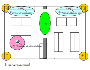
Radio wave environment measurement
The radio wave state is confirmed at four corners and the cente r of the floor where the installation of the access point is required. However, increase t he measurement point according to the area of the floor. It is confirmed whether the disturbance noise and other acces s points exist by observing th e radio wave in the range from 2400 to 2483.5MHz.
Photo1:Stable environment because of low noise floor
The radio wave is hardly observe d in the frequency band for wir eless LAN. The access point can be installed withoutb trouble.
Photo2:The high noise floor in the whole / Some fine spectra
The disturbance noise is observed in the whole of the frequency band where the wireless LAN is used. Moving a spectrum analyzer, the place where the disturbance noise becomes bigger is found, and then the place and the cause are specified.
*When the place is specified, set the calculation [CALC] to NORM so that the data is updated at each scanning. Try the means to reduce the disturbance noise if possible. If i mpossible, move the access point to a point which is away enough from the initial place.
There seems to be no influence to the communication if the leve l of the disturbance nois e is very lower than output of the access point.
Photo3:The upsurge in a part
When another access point exists near, a new access point should be installed at the place without interference after the frequency used (channel) is specified.
Photo4:The spectrum like a big mountain
When the equipment such as a microwave oven exists near, the ra dio wave of large level as shown in photo4 is discharged while it is used.
Therefore, install the access po int in a place as possible as a way from such equipment.
Decision of channel
The frequency band where there is little disturbance noise is found by measuring the radio wave state, and then the channel number is decided.
Refer to “Channel table of wireless LAN” in Table1 regarding the rela tion of channel and frequency.
photo5:Stable environment because of low noise floor
The channel can be freely set when there is no disturbance noise.
When two or more access points are installed, select the channels which are away from each other at 20MHz or more so that each radio wave isn’t interfered.
Photo6:The upsurge in a part
When there is an access point around, set the channel which is away from the center frequency of the existed access point at 20MHz or more.
When the same channel as the existed access point is used, inst all in the plach which is away enough from the access point so that there is no interference.
In case of photo6, use the channel number ofu five or more because the center frequency is 2.4132GHz (channel1).
Photo7:The spectrum like a big mountain
When the noise of the specific frequency (in this case, it is a microwave oven) is discharged, install the access point in the place which is away from the noise source and where there is no noise.
However, the communication state becomes bed if the level of the disturbance noise is not low enough. In photo7, the channel5 can be used because the noise level in the frequency band from 2.42GHz to 2.44GHz is low.
Table1 Channel table of wireless LAN
| Channel | Center frequency (GHz) | Frequency range used (GHz) |
|---|---|---|
| Channel1 | 2.412 | 2.402 to 2.422 |
| Channel2 | 2.417 | 2.407 to 2.427 |
| Channel3 | 2.422 | 2.412 to 2.432 |
| Channel4 | 2.427 | 2.417 to 2.437 |
| Channel5 | 2.432 | 2.422 to 2.442 |
| Channel6 | 2.437 | 2.427 to 2.447 |
| Channel7 | 2.442 | 2.432 to 2.452 |
| Channel8 | 2.447 | 2.437 to 2.457 |
| Channel9 | 2.452 | 2.442 to 2.462 |
| Channel10 | 2.457 | 2.447 to 2.467 |
| Channel11 | 2.462 | 2.452 to 2.472 |
| Channel12 | 2.467 | 2.457 to 2.477 |
| Channel13 | 2.472 | 2.462 to 2.482 |
| (Channel14) | 2.484 | 2.474 to 2.494 |
*The range of center frequency ±10MHz is used in each range.
Products introduction

Please feel free to contact us.
If you want to verify 5G, customize a radio wave shield box, or need product repair, please do not hesitate to contact us about any small matter.