Measurement Procedures
- Read out the cable characteristics from USB memory
- Set the rough value of distance to discontinuity point or cable length
- Press the “CF/SPAN: Auto Set” key
- Select either
- In case of 50Ω:Equip MA430 with 50Ω terminator
- In case of 75Ω:Equip with adapter cable MC313 and 50Ω/75Ω adapter MA310. Equip with MA310 75Ω terminator.
- Execute the normalization
- Remove the terminator and connect the cable under test.
A waveform of the cable in frequency domain is observed
- Switch the mode to distance domain (Execute the Inverse Fourier Transform)
These processes are executed in MSA438TG automatically
$$
\begin{cases}
・\text{IFT}:
\\ \quad
f(t)=\frac {1}{2π} \int_{-∞}^∞ F(jω) -exp[jωt]dω
\\
・\text{The time domain data is obtained}:
\\
・\text{The time domain data is transformed into the distance domain}:
\\ \quad
\text{Distance=Time×(Propagation velocity)}\\
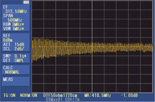
・\text{A waveform on distance domain is displayed}
\\
\end{cases}
$$
image:A waveform on distance domain is displayed
- Measure the distance to the discontinuity point with a marker
- Save the measurement result in the USB memory
Data saved in USB memory-
Parameters related to measurement
DTF Relative Propagation Velocity 0.659 Nominal Attenuation (dB/m) at 1GHz 0.787 Cable Attenuation(dB/m) 0.00 Cable Length (m) 15 Length SPAN (m) 98.84 Factory Name BLD Cable Type RG58A 58C START f (MHz) 62.5 STOP f (MHz) 562.5 -
1001 points waveform data on distance domain
spect_DTF 0 0 -47.84 ~ ~ ~ 1000 98.84 -56.13
-
Principle of DTF measurement
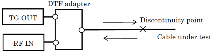
For this measurement, “TG OUT” of MSA438TG is divided into the cable under test and “RF IN” of MSA438TG by the DTF adapter. When a discontinuity point exists, the reflected signal returns to the DTF adapter. The half of reflected signal is input to the “RF IN” thorough the DTF adapter. The combined two signals of this reflected signal and “TG OUT” are input to “RF IN”. The mutual interference occurs corresponding to the frequency and the distance to discontinuity point of the cable. Therefore, peaks and bottoms are continuously generated on the frequency axis, and its frequency corresponds to the distance to discontinuity point. The reflection at the discontinuity point appears as a peak when this frequency domain data are converted into the time domain data by the inverse Fourier transform. And after then, the distance to discontinuity point is gotten by the multiplication of the appearance time of the peak and the propagation velocity. As the horizontal axis value of the marker measurement, the distance is displayed instead of the frequency in spectrum analyzer mode. Therefore, the distance can be directly read when the marker is moved to the peak. The processing mentioned above is done at each sweep.

Please feel free to contact us.
If you want to verify 5G, customize a radio wave shield box, or need product repair, please do not hesitate to contact us about any small matter.